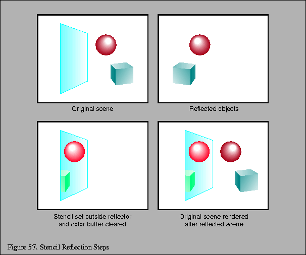
The effects of specular reflection can be approximated by a two-pass technique using the stencil buffer. The reflected scene is rendered during the first pass, and the non-reflected scene is rendered during the second pass, using the stencil buffer to clear parts of the reflected image outside the mirror polygon.
The sequence of steps for the first pass is as follows:
The application and removal of the mirror transformation can be easily applied as part of the modeling transformation stack, like OpenGL's GL_MODELVIEW matrix stack using glPushMatrix() and glPopMatrix().
Objects drawn in the first pass look as they would when seen in the mirror, ignoring the fact that the mirror may not fill the entire field of view. For the purpose of rendering, imagine that the entire plane containing the mirror is reflective, but in reality the mirror does not cover the entire plane, and so parts of the scene may be drawn which will not be visible. For example, the lowest box in the scene in Figure 55 is drawn in the reflected scene, but its reflection is not actually visible in the mirror. The second pass draws over the parts of the reflection which are not normally visible.
When rendering the reflected scene, points on the plane of the reflector maintain the same position in eye space as when rendered without reflection. For example, the corners of the reflective polygon are in the same location when viewed from the reflected eye point as from the original viewpoint. In this way, it may be more intuitive to think of reflecting the scene, rather than the eye point.
It's important to configure a clipping plane in the plane of the mirror polygon, so geometry that is behind the mirror, and subsequently is reflected in front of the mirror, is not rendered.
Do not render the mirror during the first pass or it will obscure the reflected image. This problem is most easy solved by keeping track of the mirror polygon and skipping it during rendering. This should be simple because the algorithm already has to find the mirror object and its associated data.
A special effect created by a magnified or minified reflection can be implemented by moving the scene backwards or forwards along a vector perpendicular to the plane of the mirror. This scaling looks at first glance like a concave or convex mirror, respectively, but should not be expected to survive inspection. If the position is the same distance as the eye point from the mirror then the result is an image of the same scale.
Next, clear both the depth and stencil buffers, leaving the color buffer intact. Render the mirror polygon into the stencil buffer to mask out portions of the reflected scene which were drawn in the first pass and should remain visible. Configure the stencil test to pass outside the mirror polygon and clear the color buffer, so that pixels outside the mirror return to the background color. Finally, disable the stencil test and render the remainder of the scene normally.
The list of steps for the second pass, using OpenGL, is as follows.
    glStencilOp(GL_REPLACE, GL_REPLACE, GL_REPLACE);
    glStencilFunc(GL_ALWAYS, 1, 1);
    glEnable(GL_STENCIL_TEST);
    glStencilOp(GL_KEEP, GL_KEEP, GL_KEEP);
    glStencilFunc(GL_NOTEQUAL);
These steps are illustrated in Figure 57.
It is possible to clear the stencil buffer and draw the reflector into stencil first, marking the stencil buffer where the reflection should be drawn. However, drawing the entire scene with stencil testing enabled is likely to result in lower performance than using stencil just to clear the screen all at once. A technique is presented later which requires setting stencil first to render interreflections.
The planar mirror reflector typically takes up a small region of the screen. Software that support culling to the viewing frustum can use a reduced frustum that tightly bounds the screen-space projection of the reflector when drawing the reflected scene, reducing the number of objects to be processed.

See Section 3 for more information on modeling.