An alternative to supplying the reflection vector through glTexCoord3f() is using the NV_reflection_vector extension's capability to generate automatically the eye-space reflection vector for the (s,t,r) texture coordinates. Recall that this is the same extension used in Section 6.15 though we are generating the reflection vector instead of the normal vector. Assuming the extension is available, here is how to generate the eye-space reflection vector as a 3D texture coordinate:
  glTexGeni(GL_S, GL_TEXTURE_GEN_MODE, GL_REFLECTION_MAP_NV);
  glTexGeni(GL_T, GL_TEXTURE_GEN_MODE, GL_REFLECTION_MAP_NV);
  glTexGeni(GL_R, GL_TEXTURE_GEN_MODE, GL_REFLECTION_MAP_NV);

  glEnable(GL_TEXTURE_GEN_S);
  glEnable(GL_TEXTURE_GEN_T);
  glEnable(GL_TEXTURE_GEN_R);
Here is how to set up OpenGL's texture matrix given the transformation described
above:
  GLfloat mapMatrix[16] = {
    0.5, 0,   0,  0,
    0,   0.5, 0,  0,
    0,   0,   1,  0,
    0.5, 0.5, 0,  1
  };
  GLfloat projectMatrix[16] = {
    1,  0,  0,  0,
    0,  1,  0,  0,
    0,  0,  1,  1,
    0,  0,  0,  0
  };
  GLfloat diffFrontMatrix[16] = {
    -1,  0,  0,  0,
     0, -1,  0,  0,
     0,  0,  1,  0,
     0,  0, -1,  1
  };
  GLfloat diffBackMatrix[16] = {
    1,   0,  0,  0,
    0,  -1,  0,  0,
    0,   0,  1,  0,
    0,   0,  1,  1
  };
  GLfloat mv[16], ilmv[16];

  glGetFloatv(GL_MODELVIEW_MATRIX, mv);
  mv[3]  = 0;
  mv[7]  = 0;
  mv[11] = 0;
  mv[12] = 0;
  mv[13] = 0;
  mv[14] = 0;
  mv[15] = 1;
  invert_matrix(mv, ilmv);

  glMatrixMode(GL_TEXTURE);
  glLoadIdentity();
  glMultMatrixf(mapMatrix);
  glMultMatrixf(projectMatrix);
  if (frontSide)
    glMultMatrixf(diffFrontMatrix);
  else
    glMultMatrixf(diffBackMatrix);
  glMultMatrixf(ilmv);

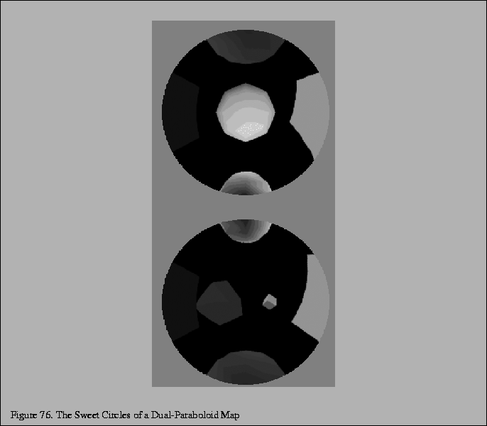
Note that each dual-paraboloid texture contains an incomplete version of the complete environment. There is some overlap between the two texture maps as shown in Figure 75 in the corners of each image. Notice that the corner region in one map are distorted so that the other map has a better sampled version of the same information. Moreover, there is some information in each map that is simply not in the other map. The information in the center of each map is only in a single map. Figure 76 shows that each map has a centered circular region where texels within the region are better sampled than the corresponding texels for the same reflection vector in the other map if the corresponding texels are available in the other map at all. We call this centered circular region of each dual-paraboloid map the sweet circle.
What remains to be done is making sure that the front dual-paraboloid map is used for pixels best sampled from the front dual-paraboloid map and vice versa. In the projective transformation discussed above, if a reflection vector falls within the sweet circle of one dual-paraboloid map, it will be guaranteed to fall outside the sweet circle of the opposite map.
With OpenGL's alpha testing capability, we can discard texels outside the sweet circle of each texture. The idea is to encode in the alpha channel of each dual-paraboloid texture an alpha value of 1.0 if the texel is within the sweet circle and 0.0 if the texel is outside the sweet circle. Be conservative about whether a texel is inside the circle to avoid in cracks the transition between the two maps.
Now, we can render an object in two passes. First, bind to the
front dual-paraboloid texture and use a ![]() value of (0,0,-1) when constructing the
texture matrix. Then in a second pass, bind to the back dual-paraboloid texture and
use a
value of (0,0,-1) when constructing the
texture matrix. Then in a second pass, bind to the back dual-paraboloid texture and
use a ![]() value of (0,0,1) when constructing the texture matrix.
During both passes, enable alpha testing to eliminate fragments with an
alpha value less than 1.0. Set up the texture environment
to make the fragment's alpha value be the texture's alpha value.
The result is a complete dual-paraboloid mapped object.
value of (0,0,1) when constructing the texture matrix.
During both passes, enable alpha testing to eliminate fragments with an
alpha value less than 1.0. Set up the texture environment
to make the fragment's alpha value be the texture's alpha value.
The result is a complete dual-paraboloid mapped object.
When multitexturing is available, the two passes can be collapsed into a single multitextured rendering pass. As described in Section 6.2, each texture unit has its independent texture matrix. We load the first texture unit to use the front texture matrix and the second texture unit to use the back texture matrix. The first texture unit uses a GL_REPLACE texture environment while the second texture unit uses a GL_BLEND texture environment. This effect is to blend the two textures based on the alpha component of the second texture. One side benefit of the multitextured approach is that the transition between the two dual-paraboloid map textures is harder to notice. Even with simple alpha testing the seam is quite difficult to notice.