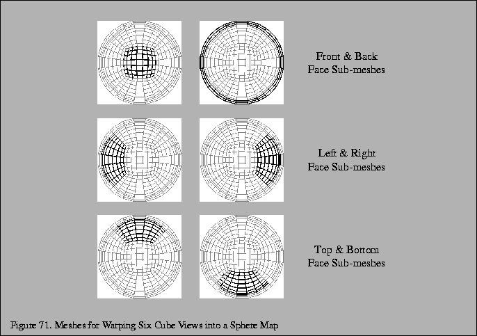
Now, a textured mesh can be drawn to form the actual sphere map. Each one of the six faces becomes a subregion of the mesh. Figure 71 shows the relationship of the submesh for each cube face view to the entire sphere map mesh. The finer the tessellation of the mesh is, the better the warping. In practice, the mesh does not have to be very fine for constructing usable sphere maps.

To render the mesh, first map locations on the cube view faces to unnormalized
reflections vectors. Think of each location on a cube view face as a
2D coordinate (u,v) where both u and v range between [-1,1].
For example, consider a particular location
(0.3,-0.4) on the Y=-1 plane
face (assuming the front cube view face is oriented on the Z=+1 plane
so as to face the viewer). This
location is mapped to the unnormalized reflection vector
(0.3,-1.0,-0.4). Normalize
this vector and consider it ![]() .
Then with this
.
Then with this ![]() ,
compute (s,t) using Equations 8 and 9.
,
compute (s,t) using Equations 8 and 9.
Treat (s,t) as a 2D vertex position in the range [-1,1] by [-1,1]. Scale by one half and bias by one half the original 2D coordinate, the (0.3,-0.4) coordinate in our example, to map it into the standard [0,1] by [0,1] texture image range. Use this remapped coordinate as a texture coordinate for the 2D vertex position. Setup an orthographic view mapping the [-1,1] by [-1,1] coordinate range into a 128 by 128 pixel region (or whatever resolution sphere map you want to create). Bind to the texture object containing the cube view face rendered image for appropriate face (the Y=-1 plane cube view face in our example). Then using the process just described for mapping from a cube face location to a reflection vector to a 2D coordinate, render a mesh of such coordinates, assigning them texture coordinates as described.
The back face mesh must be handled specially. It is not a straightforward warped rectangular patch, but instead is a mesh in the shape of a ring. You can think of the back cube view face as being pulled inside-out. In a sphere map, the center of the back cube view face becomes a singularity around the circular edge of the sphere map. The easiest way to render the back face mesh is as four meshes. The construction of these meshes is aided by the reverse mapping equations. Another issue with the back face mesh is that if a simple polygonal mesh is used, the polygonal edges will not for a perfect sphere. For this reason, it is useful to add an narrow ``extender'' mesh at the circle's edge that makes sure the entire circular sphere map region is rendered.
The meshes required are static for a fixed tessellation. You can compute the meshes once and then simply re-render the meshes for different sets of cube views. Precomputing the meshes helps reduce the overhead for repeated warping of cube face views into sphere map textures.
The final step is to copy the rendered sphere map into a texture using glCopyTexImage2D(). Once this is done, you are ready to use the newly constructed sphere map.