| (5) | |||
| (6) |
Because there is no way to directly compute the reflection point from an arbitrary tessellated reflector, an acceleration data structure called an explosion map is used to approximate the reflection point.
An explosion map stores reflection directions mapped to a 2D image, in much the same way as OpenGL maps reflection directions to a sphere map, discussed in more detail below. A unit vector x,y,zis mapped into coordinates s,t within a circle inscribed in a explosion map with radius r using Equation 5 and 6.
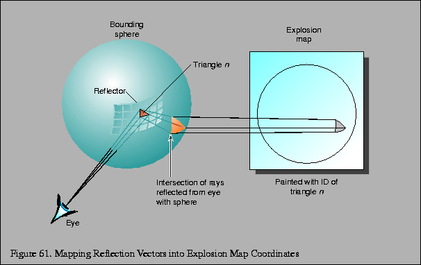
The reflection directions used in the mapping are not the actual reflection rays determined from the reflector vertex and the viewpoint. Rather, the reflection ray is intersected with a sphere and the normalized vector from the center of the sphere to the intersection point is used instead. There is a one-to-one between reflection vectors from the convex reflector and intersection points on the sphere, as long as the sphere encloses the reflector. Figure 61 shows a viewing vector V and a point P on the reflector that forms the reflection vector R as a reflection of V. The normalized direction vector D from the center of a sphere to the intersection of R with that sphere is inserted into the equation shown above.

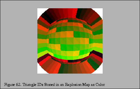
Once the reflection directions are mapped into 2D, an identifier for each triangle is rendered into the explosion map using the mapped vertices for that triangle. This provides an exact mapping from any point on the sphere to the point that reflects that point to the viewpoint. This identifier may be mapped using the color buffer or depth buffer or both as necessary. Applications will need to verify the resolution available in the frame buffer and will likely need to disable dithering. If the color buffer is used, the most significant bits of each component will be used as the least significant bits may not be stored at all and will be extended from the more significant bits on readback.

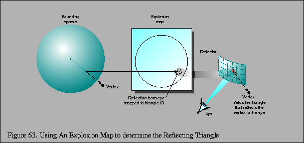
Imagine that a vertex of a face to be reflected lies on the sphere. (This is not typically the case, and will be addressed in the next paragraph.) For this vertex on the sphere, the explosion map can be used to find a reflection plane across which the vertex is reflected. The normalized vector pointing from the sphere center to the vertex is mapped into the explosion map to find a triangle ID. The mapped point formed from the vertex and the mapped triangle vertices are used to compute barycentric coordinates. These coordinates are used to interpolate a point and normal within in the triangle which approximate a plane and normal on the curved reflector. The mapped vertex is reflected across this plane to form a virtual vertex. This process is illustrated in Figure 63.

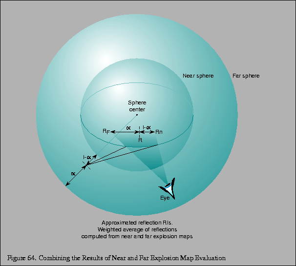
Since it is likely impossible to determine a sphere on which all vertices in the scene lie, two separate explosion maps with two spheres are computed. One sphere tightly bounds the reflector object, and one sphere bounds the entire scene. The normalized vector from the center of each sphere to the vertex is used to look up the reflecting triangle in the associated explosion map. Neither triangle may be correct, but the reflected virtual vertex is approximated by constructing virtual vertices using the results of each explosion map, and then interpolating between the two with a weight determined by the ratios of the distance from the surface of each sphere to the original vertex. Figure 64 shows how the virtual vertices determined from the explosion maps representing the near and far spheres are interpolated to find the final approximated reflected vertices.

Because the reflection directions from triangles in the reflector will not typically cover the entire explosion map, extension polygons will need to be constructed which extend the reflection mappings to cover the map. These extension polygons can be thought of as extending the edges of profile triangles in the reflector into quadrilaterals that fully partition space so that all vertices in the original scene are reflected by some polygon.
In the case that the reflector is modeled from a solid object, extension quadrilaterals may be formed from triangles in the reflector that have two vertex normals that face away from the viewer. Because the reflector is defined to be convex, these triangles automatically lie on the boundary of the front-facing triangles in the reflector. The normals of each vertex are projected into the plane perpendicular to the viewer at that vertex, which guarantees that the reflection vector from the normals maps into the explosion map. This profile triangle is projected into the explosion map using these ``fixed up'' coordinates. The edge formed by the ``fixed up'' vertices is extended to a quadrilateral to cover the remaining explosion map area, which is rendered into the explosion map with the profile triangle's identifier. It is enough to extend these vertices just beyond the boundary of the explosion map before rendering this quadrilateral.
If the reflector is a surface and is not guaranteed to have back-facing polygons, it is necessary to extend the actual edges of the reflector until normals along the edge of the reflector fully span the space of angles in the X-Y plane.