The per-vertex lighting model used in OpenGL assumes that the surface has microscopic facets that are uniformly distributed in any direction on the surface. That is to say, they assume isotropic lighting behavior.
Some surfaces have a directional grain, made from facets that are formed with a directional bias, like the grooves formed by sanding or machining. These surfaces demonstrate anisotropic lighting, which depends on the rotation of the surface around the normal to the surface. At normal distances, the viewer does not see the facets or grooves, but rather sees the overall lighting effect from such a surface. Some everyday surfaces that have anistropic lighting behavior are hair, satin Christmas tree ornaments, brushed alloy wheels, CDs, cymbals in a drum kit, and vinyl records.
Heidrich and Seidel present a technique in [50] for rendering surfaces with anisotropic lighting, based on the scientific visualization work of Zöckler et al [92]. The technique uses 2D texturing to provide a lighting solution based on a ``most significant'' normal to a surface at a point.
The algorithm uses a surface model with infinitely thin scratches or
threads that run across the surface. The tangent vector ![]() defined per-vertex can be thought of as the direction of brush
strokes, grooves, or threads. An infinitely thin thread can be
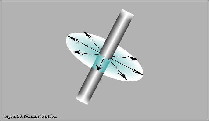
considered to have an infinite number of surface normals distributed
in the plane perpendicular to
defined per-vertex can be thought of as the direction of brush
strokes, grooves, or threads. An infinitely thin thread can be
considered to have an infinite number of surface normals distributed
in the plane perpendicular to ![]() ,
as shown in
Figure 50. In order to fully model the
light reflected from these normals, the lighting equation would need
to be integrated over the normal plane.
,
as shown in
Figure 50. In order to fully model the
light reflected from these normals, the lighting equation would need
to be integrated over the normal plane.

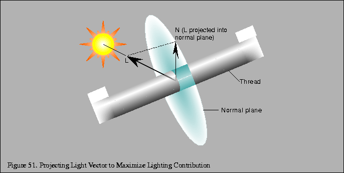
Rather than integrate the lighting equation, the technique makes
the assumption that the most significant light reflection is from the
surface normal ![]() with the maximum dot product with the light
vector
with the maximum dot product with the light
vector ![]() as seen in Figure 51.
as seen in Figure 51.

The diffuse and specular lighting factors for a point based on
the view vector ![]() ,
normal
,
normal ![]() ,
light reflection vector
,
light reflection vector
![]() ,
light direction
,
light direction ![]() ,
and shininess exponent s are
shown below:
,
and shininess exponent s are
shown below:
In order to avoid calculating ![]() and
and ![]() ,
the following
substitutions allow the lighting calculation at a point on a fiber
to be evaluated with only
,
the following
substitutions allow the lighting calculation at a point on a fiber
to be evaluated with only ![]() ,
,
![]() ,
and the fiber
tangent
,
and the fiber
tangent ![]() (anisotropic bias):
(anisotropic bias):
If ![]() and
and ![]() are stored in the
first two rows of a transformation matrix, and
are stored in the
first two rows of a transformation matrix, and ![]() is transformed
by this matrix, the result is a vector containing
is transformed
by this matrix, the result is a vector containing
![]() and
and
![]() .
After applying this transformation,
.
After applying this transformation, ![]() is computed as sand
is computed as sand ![]() is computed as t, as shown in
Equation 3 A scale and bias must also be included
in the matrix in order to bring the dot product range [-1, 1] into
the range [0, 1). The resulting texture coordinates can be
used to index a texture storing the precomputed lighting equation.
is computed as t, as shown in
Equation 3 A scale and bias must also be included
in the matrix in order to bring the dot product range [-1, 1] into
the range [0, 1). The resulting texture coordinates can be
used to index a texture storing the precomputed lighting equation.
If the further simplifications are made that the viewing vector is
constant (infinitely far away) and that the light direction is also constant,
then the results of this transformation can be used to index a 2D texture
to evaluate the lighting equation based solely on providing ![]() at
each vertex.
at
each vertex.
The application will need to fill the texture with the results of the
lighting equation (shown in Equation 17 in Appendix C.2)
with the s and t coordinates scaled and biased back to the range
[-1, 1] and evaluated in the equations above to compute ![]() and
and
![]() .
.
A transformation pipeline typically transforms surface normals into
eye space by premultiplying by the inverse transpose of the viewing
matrix. If the anisotropic bias ![]() is defined in model space,
it is necessary to query or precompute the current modeling
transformation and concatenate the inverse transpose of that
transformation with the transformation matrix computed above.
is defined in model space,
it is necessary to query or precompute the current modeling
transformation and concatenate the inverse transpose of that
transformation with the transformation matrix computed above.
Because result of this lookup is not the complete anisotropic computation but rather the ``most significant'' component of it, it may be necessary to raise the diffuse and specular lighting factors used in the lighting computation to a large fractional power. (Since those factors will be less than one, a fractional power will increase the factors.) This may result in a more visually acceptable image.
OpenGL's texture matrix (glMatrixModeGL_TEXTURE(GL_TEXTURE)) and
vertex texture coordinate (glTexCoord()) can be used to perform the
texture coordinate computation directly. The transformation is stored
in the texture matrix and ![]() is transmitted using glTexCoord()
directly.
is transmitted using glTexCoord()
directly.
Keep in mind, however, that there is no normalization step in the OpenGL texture coordinate generation system. If the modeling matrix is concatenated as mentioned previously, the coordinates must be transformed and normalized before transmission.
Because the anisotropic lighting approximation given does not take self-shadowing into account, the texture color will also need to be modulated with a saturated directional light. This will clamp the lighting contributions to zero on parts of the surface facing away from the light.
This technique uses per-vertex texture coordinates to encode the anisotropic direction, so it also suffers from the same per-vertex lighting artifacts in the isotropic lighting model. In addition, if a local lighting or viewing model is desired, the application must calculate L or V, compute the entire anisotropic lighting contribution, and apply it as a vertex color, which frees the texture stage for another use.
Because a single texture provides all the lighting components up front, changing any of the colors used in the lighting model requires recalculating the texture. If two textures are used, either in a system with multiple texture units or with multipass, the diffuse and specular components may be separated and stored in two textures, and either texture may be modulated by the material or vertex color in order to alter the diffuse or specular base color separately without altering the maps. This can be used, for example, in a database containing a precomputed radiosity solution stored in the per-vertex color. In this way, the diffuse color can still depend on the orientation of the viewpoint relative to the anisotropic bias but only changes within the maximum color calculated by the radiosity solution.