If you have never seen OpenGL before, please read first the Getting Started with OpenGL tutorial.
Here we move on to 3D... where things get just a little more complex.
Essentially, a perspective projection. You CAN use orthographic projections in 3D, but the results won't be realistic. Just bear in mind that there are uses for that.
This will require us to change our sample program as follows:
int main(int argc, char **argv)
{
	...
	glMatrixMode( GL_PROJECTION );
	glLoadIdentity();
	gluPerspective( 90,1.0,0.1,100 );
	glMatrixMode( GL_MODELVIEW );
	...

	glutMainLoop();
}
|
Basically, we switched the gluOrtho(..) call for a gluPerspective(...) call. This requires the specification of a field of view (90 degrees, in this example), aspect ratio (1 as default), near clipping plane (0.1) and far clipping plane (100).
The aspect ratio is needed to adjust the proportions of the displayed image to the window dimensions - you will see in a moment how this works.
Those clipping planes are the shortest and longest distances that objects will show (from the observer point of view). So in this case, nothing that lies BEFORE 0.1 units and AFTER 100 units from the observer will be seen.
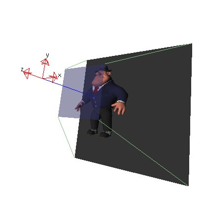
The following image shows how these parameters are used - the transparent square is the near clipping plane and the opaque one is the far clipping plane.
This also shows the orientation of the axes in 3D: note that Z points outwards.
Also we will usually need a Z-Buffer, to get rid of those hidden surfaces (the ones that are not facing the observer, or being blocked by others). This is set in glutInitDisplayMode:
int main(int argc, char **argv)
{
	glutInitDisplayMode( GLUT_RGB | GLUT_DOUBLE | GLUT_DEPTH );
	...
|
Some things are tricky in OpenGL - even if we have already ASKED for a Z-buffer, we need to explicitly ENABLE it:
int main(int argc, char **argv)
{
	...
	glEnable(GL_DEPTH_TEST);
	glutMainLoop();
}
|
Drawing stuff in 3D isn't much different than drawing in 2D. We just need to inform three, instead of two coordinates for each vertex - the primitives are the same.
Sounds easy ? Well, not really. It's pretty simple to figure out 2D coordinates for an object, but 3D is an entirely different matter: you have to think spatiallly!
Unless you have a REALLY good spatial perception, it's always a wise idea to use some kind of graph paper to draw a sketch of your object.
If it's too complex, try to split it in parts and work one at a time. In this example, we'll try to model a simple house.
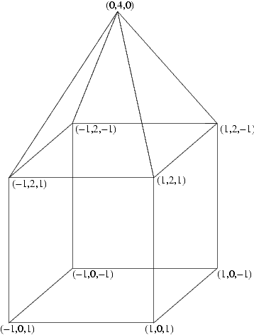
We are not really interested in adding lots of details, just getting the basic shape right - which means drawing a pyramid on top of a cube.
So let's draw a sketch first:
Now we just need to write code to draw every surface. To make sure things are working as planned, we will just draw the front face:
void draw()
{
	glClearColor( 0, 0, 0, 0 );
	glClear ( GL_COLOR_BUFFER_BIT | GL_DEPTH_BUFFER_BIT );

	glLoadIdentity();		// clear modelview

	// Drawing the cube
	glBegin(GL_QUADS);		// using quadrilaterals as primitive
	// Front
	  glColor3f( 0, 1, 0 );		// set colour to pure green
	  glVertex3f( -1,  0,  1 );
	  glVertex3f( -1,  2,  1 );
	  glVertex3f(  1,  2,  1 );
	  glVertex3f(  1,  0,  1 );
	glEnd();

	glutSwapBuffers();
}
|
Note that the glClear(...) call has been changed: we need to ask it to clear the Z-buffer (GL_DEPTH_BUFFER_BIT) as well.
Exercise: Compile and run the new code. What do you see ?
If you got a nice black screen, then yes, you did it right. Using perspective projection, everything that is supposed to show on the screen must be INSIDE it - so the Z coordinates must be negative.
Why ? Remember that the Z axis points outwards: it means that positive Zs are towards you, zero being the screen plane itself.
Thus, in order to actually see anything you'll have to either change the Z coordinates of your model OR... push everything forwards.
The latter option seems more sensible, doesn't it ?
How do we move things around ? Yes, using a translation! Let's add a simple one to the code and see what happens:
void draw()
{
	glClearColor( 0, 0, 0, 0 );
	glClear ( GL_COLOR_BUFFER_BIT | GL_DEPTH_BUFFER_BIT );

	glLoadIdentity();		// clear modelview then...
	glTranslatef( 0,-3,-8 );	// ...move forwards and down a bit

	// Drawing the cube
	glBegin(GL_QUADS);		// using quadrilaterals as primitive
	...
}
|
Exercise: Change the code then run it. Make sure that you see a green square.
Note that we also moved it down, to make room for the pyramid. Now try to maximize or stretch the window - what happens with the square ?
That is the effect of the aspect ratio parameter, mentioned before. Later, you'll have a chance to fix this as an exercise.
Now we need to code in the other quads:
void draw()
{
	glClearColor( 0, 0, 0, 0 );
	glClear ( GL_COLOR_BUFFER_BIT | GL_DEPTH_BUFFER_BIT );
	glLoadIdentity();		// clear modelview
	glTranslatef( 0,-3,-8 );	// ...move back and down a bit

	// Drawing the cube
	glBegin(GL_QUADS);		// using quadrilaterals as primitive
	// Front
	  glColor3f( 0, 1, 0 );		// set colour to pure green
	  glVertex3f( -1,  0,  1 );
	  glVertex3f( -1,  2,  1 );
	  glVertex3f(  1,  2,  1 );
	  glVertex3f(  1,  0,  1 );

	// Back
	  glColor3f( 0, 0.8, 0 );		// a slightly darker green for the back
	  glVertex3f( -1,  0, -1 );
	  glVertex3f(  1,  0, -1 );
	  glVertex3f(  1,  2, -1 );
	  glVertex3f( -1,  2, -1 );

	// Left side
	  glColor3f( 0, 0.6, 0 );		// an even darker shade for the sides
	  glVertex3f( -1,  0,  1 );
	  glVertex3f( -1,  2,  1 );
	  glVertex3f( -1,  2, -1 );
	  glVertex3f( -1,  0, -1 );

	// Right side
	  glVertex3f(  1,  0,  1 );
	  glVertex3f(  1,  0, -1 );
	  glVertex3f(  1,  2, -1 );
	  glVertex3f(  1,  2,  1 );
	glEnd();


	glutSwapBuffers();
}
|
As we are not working with lighting, it wouldn't be a good idea to use the same color for all faces.
So we used slightly different shades of green for each face (see the glColor(...) calls).
But now that the object is a real solid, we need to change our viewpoint to actually see how it looks.
The easiest way is by adding a rotation around the Y axis. We could experiment with some values, but to make things simpler
we will keep updating the rotation angle with each keypress. Doing this way, we will be able to see the object from all sides.
There is nothing special in the keyboard routine:
void keyboard(unsigned char key,int x,int y)
{
	if(key==27) exit(1);
	rot+=5;				// increment the rotation angle by 5 degrees
	rot%=360;			// ... and keep it within 0-359
	glutPostRedisplay();
}
|
But in display(), we will put the rotation around Y - vector (0,1,0) - as follows:
...
#include <GL/glut.h>

int rot = 0;		// in case you already didn't have it
...

void draw()
{
	...
	glLoadIdentity();		// clear modelview
	glTranslatef( 0,-3,-8 );	// ...move back and down a bit
	glRotatef(rot,0,1,0);		// ... and rotate a little
	...
}
|
Exercise: Change and run it. Check that the object rotates when you press a key (except ESC).
Been asking yourself why we used -1 and 1 for the X and Z vertex coordinates ?
Now you see: as the object is dead centered in X and Z (i.e. values between -1 and 1), it rotates perfectly around Y.
As a rule of thumb, always try to model your objects this way. It will be MUCH easier to move and rotate them around....
Ok, now that we made sure the object was correctly modeled, let's add the roof (pyramid):
void draw()
{
	// Drawing the cube
	glBegin(GL_QUADS);
	...
	glEnd();

	// Now the roof
	glBegin(GL_TRIANGLES);
	// Front
	  glColor3f( 1, 1, 0 );		// yellow
	  glVertex3f( -1,  2,  1 );
	  glVertex3f(  0,  4,  0 );
	  glVertex3f(  1,  2,  1 );
	// Right side
	  glColor3f( 0.9, 0.9, 0 );	// darker yellow
	  glVertex3f(  1,  2,  1 );
	  glVertex3f(  1,  2, -1 );
	  glVertex3f(  0,  4,  0 );
	// Back
	  glColor3f( 0.8, 0.8, 0 );	// even darker yellow
	  glVertex3f(  1,  2, -1 );
	  glVertex3f( -1,  2, -1 );
	  glVertex3f(  0,  4,  0 );
	// Left side
	  glColor3f( 0.7, 0.7, 0 );	// a bit darker, but still yellow
	  glVertex3f( -1,  2,  1 );
	  glVertex3f(  0,  4,  0 );
	  glVertex3f( -1,  2, -1 );
	glEnd();

	glutSwapBuffers();
}
|
Exercise: add the roof and run the program again.
Note: if you are having difficulties to understand the model, please refer to the sketch! That's its purpose, after all.
Further stuff to try:
Last modified on 29/03/2004 by Marcelo Cohen